Panel Mount Industrial Touch Panel PC Integration Checklist for Machine Builders
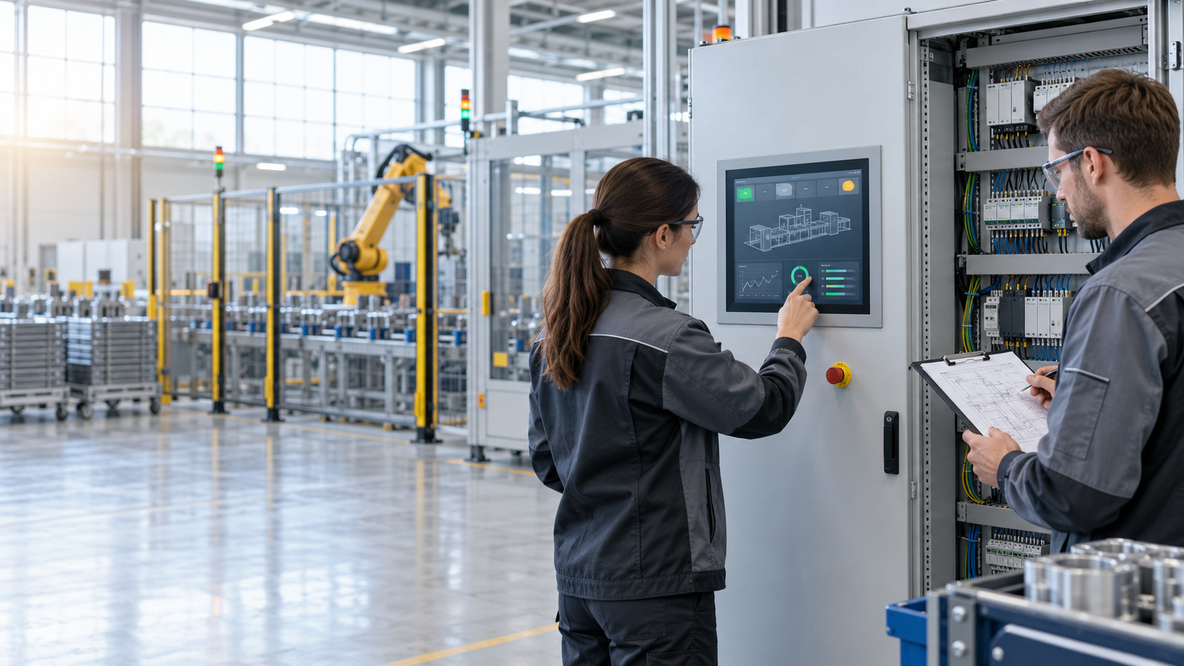
In a factory automation project, a panel mount industrial touch panel PC may appear to be a standard component. However, the issues that affect development schedules and long-term maintenance costs are often not processor speed, memory capacity or display resolution. They are the integration details discovered after the control cabinet and machine structure have already been finalized.
Is the panel cut-out correct? Is there sufficient rear clearance for the computer, connectors and cable bends? Can technicians reach the connections without removing other control components? Will the new system communicate with existing PLCs, scanners and serial devices? If a replacement unit is required several years later, can the approved operating-system image and application configuration be restored efficiently?
When these questions are addressed before the design is released, most issues can be resolved through mechanical planning, I/O selection or appropriate platform configuration. When they are discovered during final assembly, they may affect the enclosure, wiring, software and validation process.
The following ten-point checklist helps machine builders, system integrators and engineering teams establish a practical foundation before deploying a panel mount industrial touch panel PC.
Define the Application Before Selecting the Processor
The first step is not comparing CPUs. It is defining what the industrial touch panel PC must do.
A system used for basic machine control, parameter entry and alarm display has different computing requirements from a platform that simultaneously performs data logging, image processing, database access and communication with multiple factory systems.
Insufficient computing capacity may affect application performance and operator response. Excessive processing capacity may increase cost, power consumption and thermal demands without adding meaningful value.
Start by documenting the software, expected data volume, peripheral devices, concurrent processes and realistic future functions. Processor, memory and storage can then be selected against a defined workload.
The appropriate platform is not necessarily the one with the highest specifications. It is the one capable of performing the required tasks consistently throughout the intended machine lifecycle.
Confirm the Front Bezel and Panel Cut-Out
A panel mount PC is normally integrated into a control cabinet door, machine enclosure or operator console. Its front dimensions, panel cut-out and retention method must therefore be confirmed during the mechanical design stage.
Two products with the same display size do not necessarily have the same front bezel, chassis depth or cut-out requirements. Reserving space based only on the display dimension can result in an installation problem when the first machine is assembled.
The mechanical drawing should confirm:
- Overall front-bezel dimensions
- Recommended panel cut-out
- Interface between the computer and cabinet door
- Position and operating space of mounting clips
- Cabinet material and panel thickness
- Clearance from buttons, indicators and adjacent components
For a broader comparison of installation approaches, see BIS’s guide to Panel PC Mounting Options.
Reserve Rear Clearance and Service Access
Having enough space for the chassis in a CAD drawing does not guarantee practical installation.
The complete rear envelope must include the chassis, connectors, plugs, cable bend radius, mounting hardware and space for a technician’s hands and tools. If the installed cables are compressed against adjacent components, connectors may become difficult to remove and the cabinet door may not operate correctly.
A useful rear-clearance model should include:
- Actual chassis depth
- Power and signal connector length
- Cable bend requirements
- Nearby wire ducts and control components
- Space required to operate the mounting hardware
- Removal path for future replacement
This is a straightforward engineering check, but it can prevent expensive mechanical changes later.
Build an I/O Matrix Instead of Counting Ports
Factory automation equipment may connect to PLCs, sensors, barcode readers, cameras, card readers, printers, network infrastructure and established serial devices. The project team should develop a complete I/O matrix rather than merely confirming that the computer has USB, LAN and COM ports.
The matrix should document:
- Interface type and quantity
- Purpose of each connection
- Communication protocol and data requirements
- Connector position and orientation
- Cable length and retention method
- Any isolation or project-specific conditions
- Realistic future expansion requirements
The presence of a port does not automatically make it suitable. A connector positioned behind a mounting clip or too close to a wire duct can make assembly and service unnecessarily difficult.
An appropriate I/O configuration can reduce external adapters, hubs and additional wiring. This simplifies the bill of materials, reduces possible failure points and makes troubleshooting more efficient.
Validate Existing Equipment and Software
Many factory automation projects upgrade an existing control platform rather than starting from a clean design. A new computer may still need to communicate with older PLCs, serial devices, dedicated controllers or other peripherals that remain operationally valuable.
Before purchasing, validate the intended:
- Operating system and application software
- HMI or production-management program
- Peripheral drivers
- PLC and communication equipment
- Network configuration and permissions
- Automatic start-up and exception-recovery functions
- Update and restoration process
“Theoretically compatible” and “validated in the target environment” are not the same. Building a prototype with the actual software and peripherals is usually more economical than resolving compatibility issues after production begins.
Evaluate the Thermal Environment Inside the Cabinet
The operating conditions of a panel mount industrial PC are not determined only by factory room temperature. The rear chassis is commonly located inside a control cabinet containing power supplies, PLCs, drives and other heat-generating equipment.
Even when a fanless computer is selected, the project team should evaluate:
- Expected internal cabinet temperature
- Location of adjacent heat sources
- Air movement around the computer
- Obstruction of heat-dissipation surfaces
- Cabinet ventilation or cooling strategy
- Software workload and operating duration
A fanless architecture removes a mechanical moving component, but it does not replace proper thermal planning. Heat management should be addressed during cabinet design rather than treated as a corrective action after assembly.
Test Touch Operation and Ergonomics in the Real Workflow
Touch technology should be selected around the actual operating procedure, not simply by comparing technology names.
Engineers should determine whether operators wear gloves, which gestures are required, how frequently data is entered and how large the software controls need to be. Installation height, viewing angle, ambient light and reflections also affect usability.
Use the intended HMI interface during evaluation and check:
- Whether frequent controls are easy to reach
- Whether text and alarms are clearly visible
- Whether the operator can maintain a natural posture
- Whether the interface creates accidental touches
- Touch response under expected operating conditions
- Comfort during extended use
A successful user interface depends on the software, touchscreen, installation position and machine structure working together.
Design the Maintenance and Recovery Process in Advance
Once equipment enters production, the expensive part of a failure is often not the replacement computer. It is the time required to diagnose the problem, remove the system, restore the software and restart production.
The project should define:
- Who performs the initial diagnosis
- How the computer is removed from the enclosure
- Whether a replacement can use the same cut-out and cables
- Who owns and maintains the operating-system image
- How applications and settings are backed up
- How communication and functions are verified after replacement
- Which spare units or components should be held locally
Standardizing hardware platforms, software images and I/O configurations across related production lines can reduce the number of spare units and troubleshooting procedures required.
These savings may not appear in the unit purchase price, but they continue throughout the machine’s operating life.
Confirm Lifecycle and Change-Management Expectations
Industrial machinery often remains in production and service longer than consumer computing products. Lifecycle planning should therefore involve more than asking how long a specific model will be available.
The discussion should include:
- Expected production period
- Required service period
- Supply strategy for key components
- Product or component change notification
- Alternatives following end of life
- Effects on cut-outs, mounting and wiring
- Possible driver or system-image changes
- Validation responsibility after a change
Machine builders do not necessarily need hardware that never changes. They need changes that are predictable, communicated and manageable.
If every platform update requires new mechanical drawings, cable modifications and software validation, any initial purchasing savings can quickly be consumed by engineering work.
Customize Only to Remove Genuine Integration Barriers
OEM or ODM customization should solve a defined engineering problem. Depending on the selected platform and project conditions, this may involve I/O configuration, connector positioning, hardware combinations, firmware settings, system images, mounting structures or external appearance.
Before requesting customization, divide the requirements into three categories:
- Essential functions: The machine cannot operate without them.
- Efficiency improvements: They reduce assembly, deployment or maintenance work.
- Preferences: They mainly affect appearance or user familiarity.
This classification helps control development costs and validation scope. Greater customization can also mean additional drawings, sample approval, testing, material management and version-control responsibilities.
For a more detailed discussion of the customization process, refer to How to Design a Custom Industrial PC for OEM Applications.
Final Verification from Prototype to Production
After the initial platform is selected, validation should use the intended production configuration rather than a sample that is merely similar.
The verification plan should cover:
- Installation in the actual cabinet and panel
- Complete cabling and peripheral connections
- Target operating system and application software
- PLC and factory communication
- Expected computing workload
- Start-up, shutdown and exception recovery
- System-image backup and restoration
- Removal and replacement procedure
- Final bill of materials and revision records
The machine builder, system integrator and computer supplier should also establish ownership of mechanical drawings, software images, test records, change approval and production revisions.
Clear ownership reduces information gaps when the project moves from prototype to repeatable production.
Conclusion: Specifications Start the Machine; Integration Planning Keeps It Running
A panel mount industrial touch panel PC is an important interface between operators, control equipment and production information. Successful deployment requires more than finding a computer with sufficient technical specifications. The system must also fit the enclosure, connect correctly, support efficient software deployment, allow practical maintenance and remain manageable throughout its lifecycle.
For machine builders and system integrators, the most effective approach is to review mechanical integration, I/O, thermal conditions, operator workflow, maintenance and lifecycle planning before the control cabinet and software architecture are finalized.
A specification sheet explains what a product contains. A complete integration checklist determines whether that product is genuinely suitable for the machine and its production plan.
Planning a new automation machine or upgrading an existing control platform? Share your cabinet drawings, I/O list, software requirements, operating environment and estimated volume with BIS to discuss an appropriate panel mount industrial touch panel PC and OEM or ODM integration approach.
Q1:
What information should be confirmed before selecting a panel mount industrial touch panel PC?
A1:
Confirm the application software, computing workload, panel cut-out, rear clearance, I/O list, peripheral compatibility, operating environment and maintenance process before selecting the processor, memory and storage configuration.
Q2:
Why should the panel cut-out not be based only on display size?
A2:
Products with the same display size may have different bezel dimensions, chassis depths, cut-outs and mounting hardware. Cabinet design should follow the confirmed mechanical drawing and include connector, cable, thermal and service clearances.
Q3:
When should OEM or ODM customization be considered?
A3:
Customization should be considered when a standard product cannot meet essential I/O, connector, mounting, hardware or software deployment requirements, and when the change provides measurable integration or maintenance value.